eepeep: Dumping an in-circuit EEPROM
While trying to reverse engineer the VidCon Youtube OnStage bracelets I had the need to access the contents of an EEPROM that is used as external storage by the main microcontroller, however I did not want to de-solder the EEPROM to get access to it so I started looking at ways to dump the contents while the EEPROM was still in-circuit.
I found a couple of articles (1,2) explaining how to access and dump EEPROMs using an Arduino but the firmware needed to be adapted for each type of EEPROM and re-flashed, and the transfer of the chip contents depended on a generic serial port application so it seemed like coming up with something more generic that could be used for a wide range of EEPROMS could be an interesting project.
eepeep was developed with the following design principles in mind:
- It needs to be open source / open hardware so it is easy for people to modify and extend it
- It needs to be easy to use (within reason, after all it is designed for reverse-engineers)
- It must support as many EEPROMs as possible out of the box
- It needs to be easy for users to contribute new EEPROM details
- It must, at least, support I2C and SPI protocols
- The client must be multiplatform and run, at least, on Windows, Linux and MacOS
- The hardware component must be affordable and easy to implement across multiple platforms
You can find the code and hardware design in the project repository.
Setting up your equipment
Start by downloading eepeep, v1.0 was just released - it has been tested on a range of EEPROMs, however your mileage may vary. Use with caution and do not use in any circuit you would mind going up in smoke, and please file any issues you encounter with it.
Put together the hardware component using the following circuit:

The circuit is just a basic setup to allow the Arduino to access the I2C bus that the EEPROM is connected to. The terminals labelled SCL, SDA, GND and 5v/3.3v will be connected to the in-circuit EEPROM, you can find more details in the Hardware design section and the detailed bill of materials in the project repository.
After assembling the circuit flash the Arduino board with this script and you are ready to go.
Dumping an in-circuit EEPROM
Start by identifying the EEPROM part number and finding a datasheet for it, this will indicate the key parameters you need to feed to eepeep to access the data stored in the device.
This is what you are after:
- Protocols supported: at the moment
eepeeponly supports dumping I2C-enabled EEPROMs - Pinout: find out the EEPROM pins for SDA, SCL, Vcc and GND.
- Voltage level: whether it will need a 3.3v or a 5v power line.
- Frequency of the I2C bus: typically 100KHz or 400KHz
- Unique I2C device address
- EEPROM size
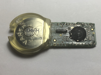
Through this article we will use the following EEPROM as the target we want to dump:

From the markings we can make out it is a 24C02S, a 2048bits serial EEPROM with a widely available datasheet. We can extract the following details from the datasheet:
- Protocols supported: it supports I2C
- Pinout: we can see the pinout for the SOT-23 package in the datasheet, we have annotated the picture above with the pins
- Voltage level: the accepted ranges mean it can operate both at 3.3v and 5v. We will stick to 5v.
- Frequency of the I2C bus: both 100KHz and 400KHz supported
- Unique I2C device address: we can see the device can be addressed from 1010000 to 1010111 (e.g. 0x50 to 0x57)
- EEPROM size: 2048 bits, e.g. 256 bytes
Remove any power source from the target circuit that the EEPROM is connected to (e.g. the one you are reverse engineering) as we will be powering the EEPROM and the I2C bus through the Arduino.
Using the pinout that you have identified connect it to the eepeep hardware component headers, using logical probes or anything else that works for you. Make sure you select the appropriate voltage header and that the pin connections are accurate, this is the only point where you can destroy the EEPROM (and the rest of the circuit it is attached to).
I have some small logical probes that are ideal for this:


Connect the Arduino to the host through USB and launch the software component, choose the serial port the Arduino is connected to and then click on “Connect”.

If all goes well you should receive a confirmation that a connection has been established to the software component, and that the hardware is ready. If you cannot see this double-check the firmware flashing was successful.

Enter the bus frequency obtained from the datasheet; if you do not have this try 100 or 400 KHz as these are the standard I2C bus frequencies.
Click on the “Scan” button to scan the I2C bus for the addresses of all valid connected devices - if your target circuit has multiple devices connected to the bus all of these will show up on the scan results:

Use the datasheet to identify which address belongs to your EEPROM module, beware as a device may have multiple addresses. If the scan result comes back empty please double-check the connection between the hardware component and the EEPROM.
Input the desired device I2C address to dump in the “Address” field and enter the start and end memory addresses to dump, typically these will be zero as the start address and the total memory size as the end address. For instance in the case of the 24c02s the I2C address is between 0x50 and 0x57 and it can hold 256 bytes of data, so we will set the memory end address to dump at 0xFF:

After you click on “Dump EEPROM contents” you will see the progress on the console output, after a while (depending on the EEPROM size) a window will pop-up asking where do you want to save the extracted EEPROM contents for further analysis.
If you use eepeep to dump a new EEPROM type we encourage you to share the parameters used for that EEPROM so that others may benefit from your work, just submit an issue with the EEPROM details so we can add it to a future version of the software.
Architecture
Software design
To meet the multiplatform requirement for the software component it has been implemented in electronjs, relying on the serialport library for communications with the hardware component. The cost of the multiplatform capability is an exagerated memory consumption (after all we are running Chromium inside the application) and a software package size close to 100MB for an application that developed in C may not take more than a few KBs.
The software has two key components: a serial protocol parser and a state machine that exchanges messages with the hardware component. The serial protocol parser has been implemented like a stream Transform and takes care of the low-level protocol implementation, including reassembly of frames and message passing to the core process. The state machine is implemented using a set of case/switch statements that ensure the client and the hardware components are kept in sync.
Hardware design
The hardware component acts as a bridge between the client and the EEPROM, implementing the bus scanning and EEPROM access protocols. At its core it is a state machine that receives messages from the client (scan bus, dump eeprom) and translates these to the I2C protocol commands that interact with the EEPROMs.
The interaction with the EEPROM happens over the I2C protocol, so the hardware circuit is a simple implementation of an I2C access setup by using a couple of 4.7k pull-up resistors.
The hardware component has been designed with simplicity in mind so it can be easily ported to other architectures, the firmware must implement the following functionality:
- Command control loop for messages coming from the software client
- I2C bus scanning
- I2C memory dump