PiArcade: All-in-one Raspberry Pi arcade controller
When I have friends over we regularly end up playing at the arcade cabinet and having a good laugh. For a while I have been tinkering with the idea of building a small self-contained Raspberry Pi powered arcade controller for them to take back home so that they can spread the arcade love :-)
The aim is not to have a replacement for an arcade cabinet or a top of the range controller, but to allow them to play arcade games without having to resort to sitting in front of a PC with MAME and a keyboard.
With this in mind I set to build a controller that would meet the following requirements:
- It needs to be self-contained: no separate components for controller and CPU
- It needs to be portable
- It should allow two simultaneous players
- It should cost less than 50 USD
- It should be easy to build, so that it can be replicated
The design is heavily based on Retrobox by Zach@HowChoo.
Components
To build the Raspberry Pi arcade controller you will need the following (or similar) components:
- Controller box, approx. USD 16
- Joystick, buttons and USB Zero Delay encoder, approx. USD 14
- Raspberry Pi 3 with power adapter and heatsinks, approx. USD 43
- SD card, approx. USD 4
- Standoffs to mount the Raspberry Pi, you can 3D print them or re-use some other filler you may have laying around
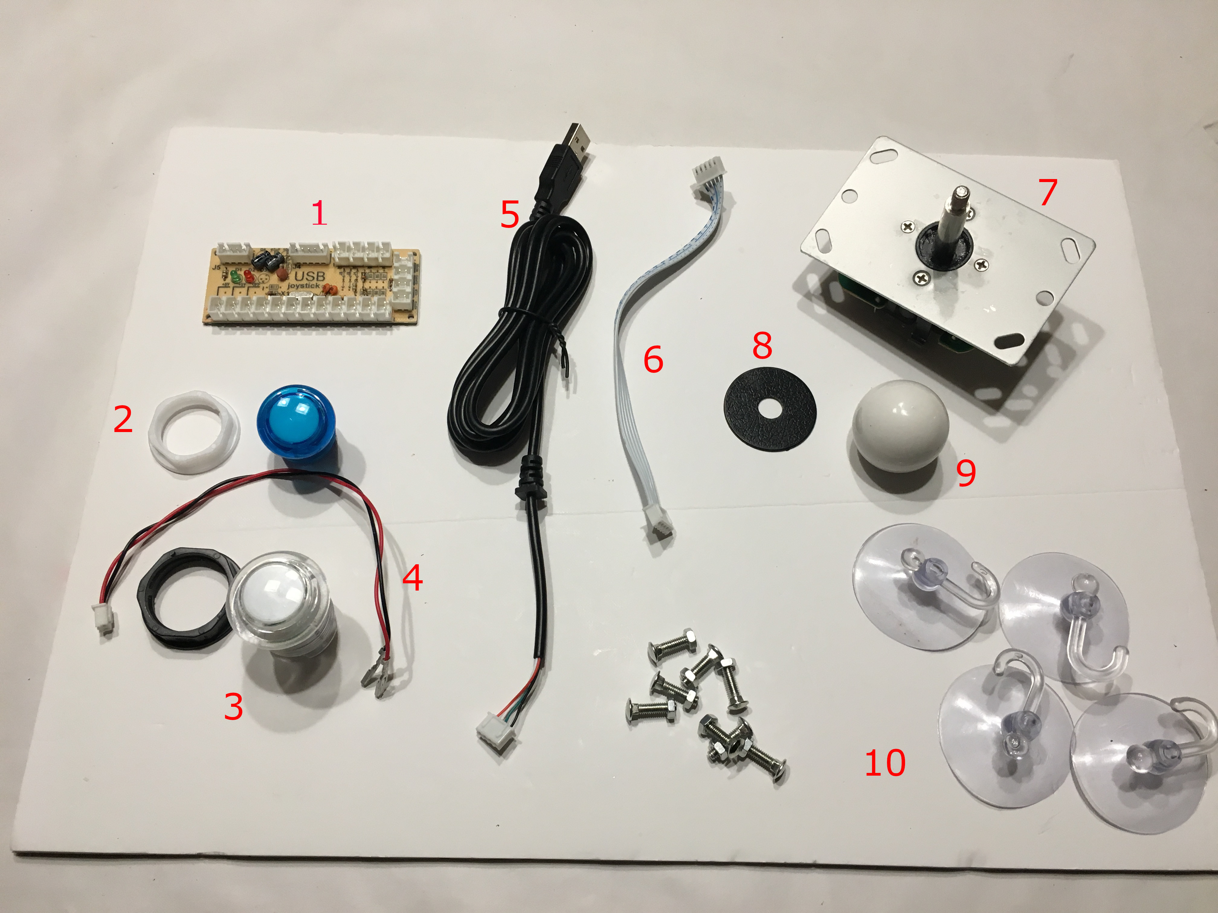
Here is a break-down of the button and joystick components:
- 1: Zero delay USB Encoder
- 2: 26mm button with plastic screw ring, used for start/coin buttons
- 3: 28mm button with plastic screw ring, used for game buttons
- 4: Cable between buttons and USB encoder
- 5: USB cable to connect encoder to Raspberry Pi
- 6: Ribbon cable between joystic and USB encoder
- 7: Joystick base, goes under the controller box lid, screwed from the top
- 8: Joystick dust cover, goes just over the controller box lid
- 9: Joystick ball, screwed at the tip of the joystick bar
- 10: Suckers, they ensure the controller box stays stuck to the table
The total price was around USD 70, as you can see most of the cost comes from the Raspberry Pi 3: you can reduce this cost by using a previous generation Pi, this will limit the number of emulators you can run but for Arcade games you should be overall fine with a Pi 2, which should bring the price closer to the target USD 50.
Controller box
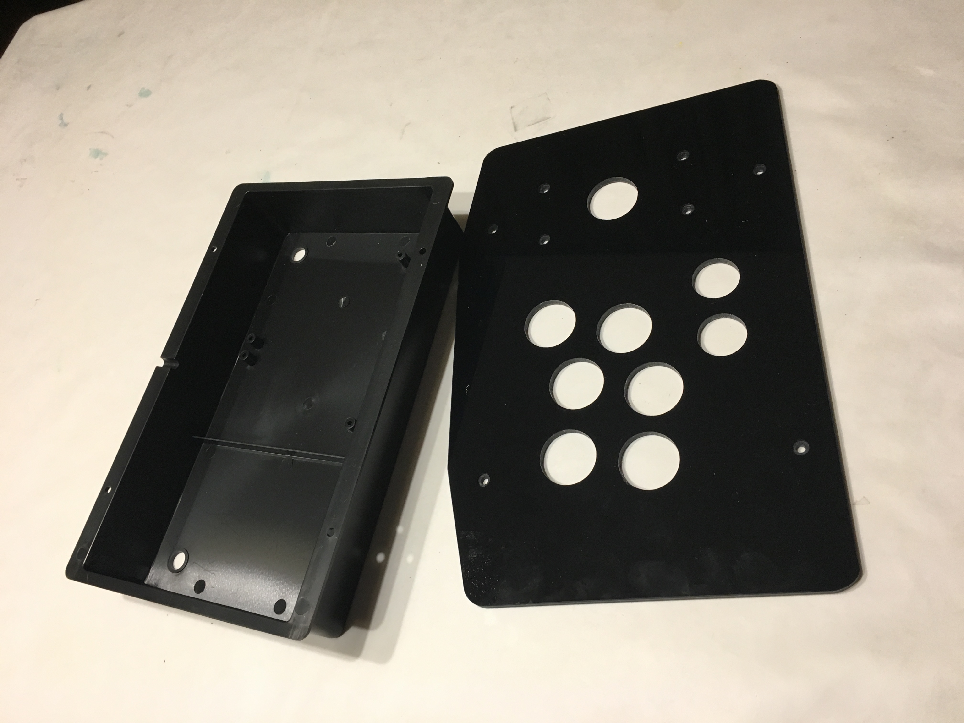
The controller box I ordered is pre-drilled with the joystick and button holes, and has a nice acrylic finish to it - nice, cheap and easy to source and build.
The most important bit for the controller box is having enough space to fit in the Raspberry Pi, you will need at least 5cm of depth and a space clear of buttons and the controller of at least the same size as the Raspberry Pi. If you buy the controller linked from above you will have just enough space to fit in the Raspberry Pi.
Another nice feature of the controller box I purchased was the “suckers” that allow the controller to be firmly stuck to a tabletop - as it does not weight that much the extra stability is welcome.
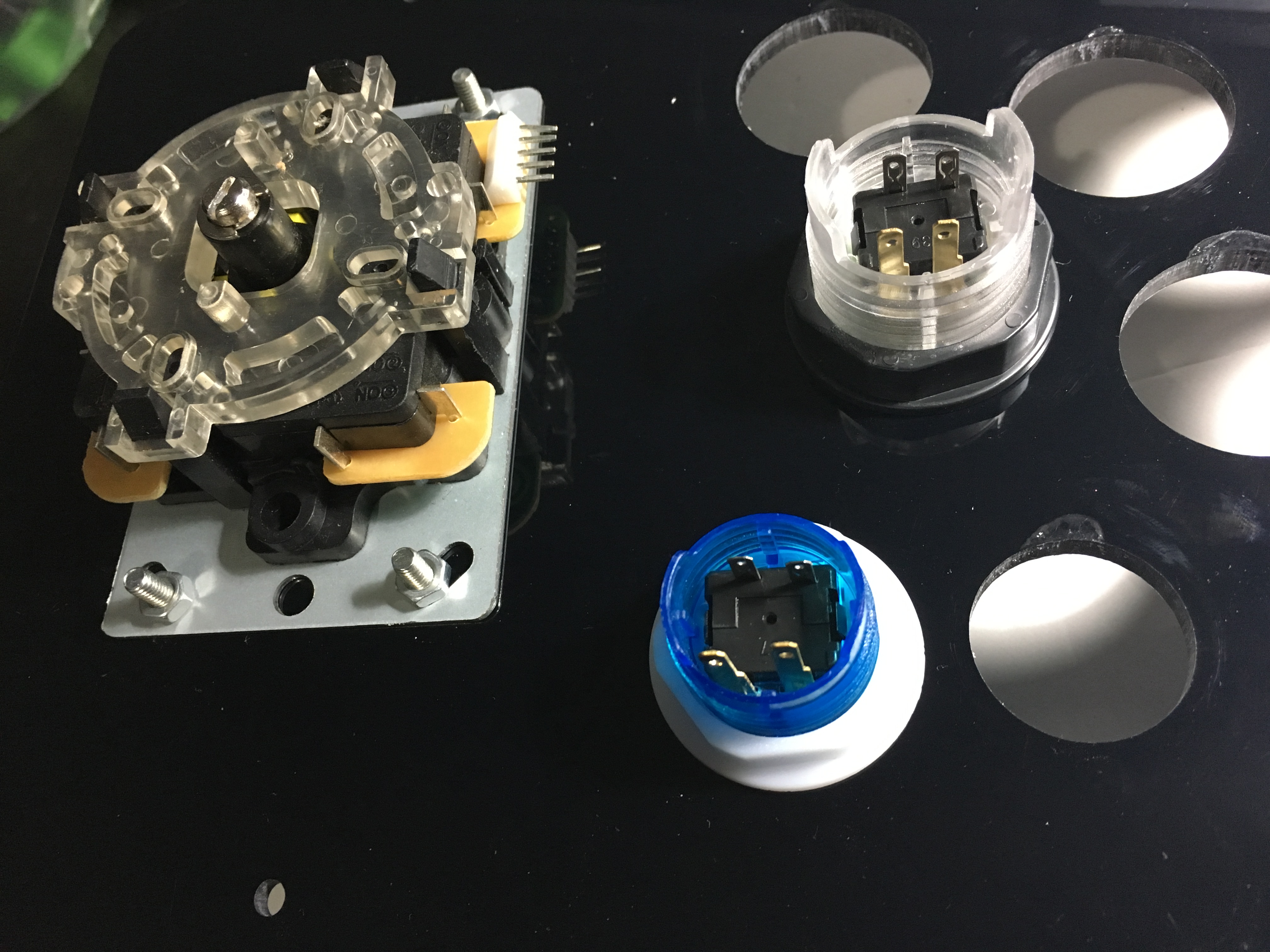
Mount the buttons and the joystick to the controller box cover, this will depend on your controller box and the buttons/joystick you have purchased, but generally:
-
buttons: insert the buttons through the controlled box hole and then screw the ring from the inside. You may have different sizes for the two “option buttons” that we will use for “coin” and “game start”.
-
joystick: remove the ball by unscrewing it and its dust cover. Mount the joystick through, replace the dust cover and then screw the ball on top. Secure the joystick to the controller box using the provided screws.
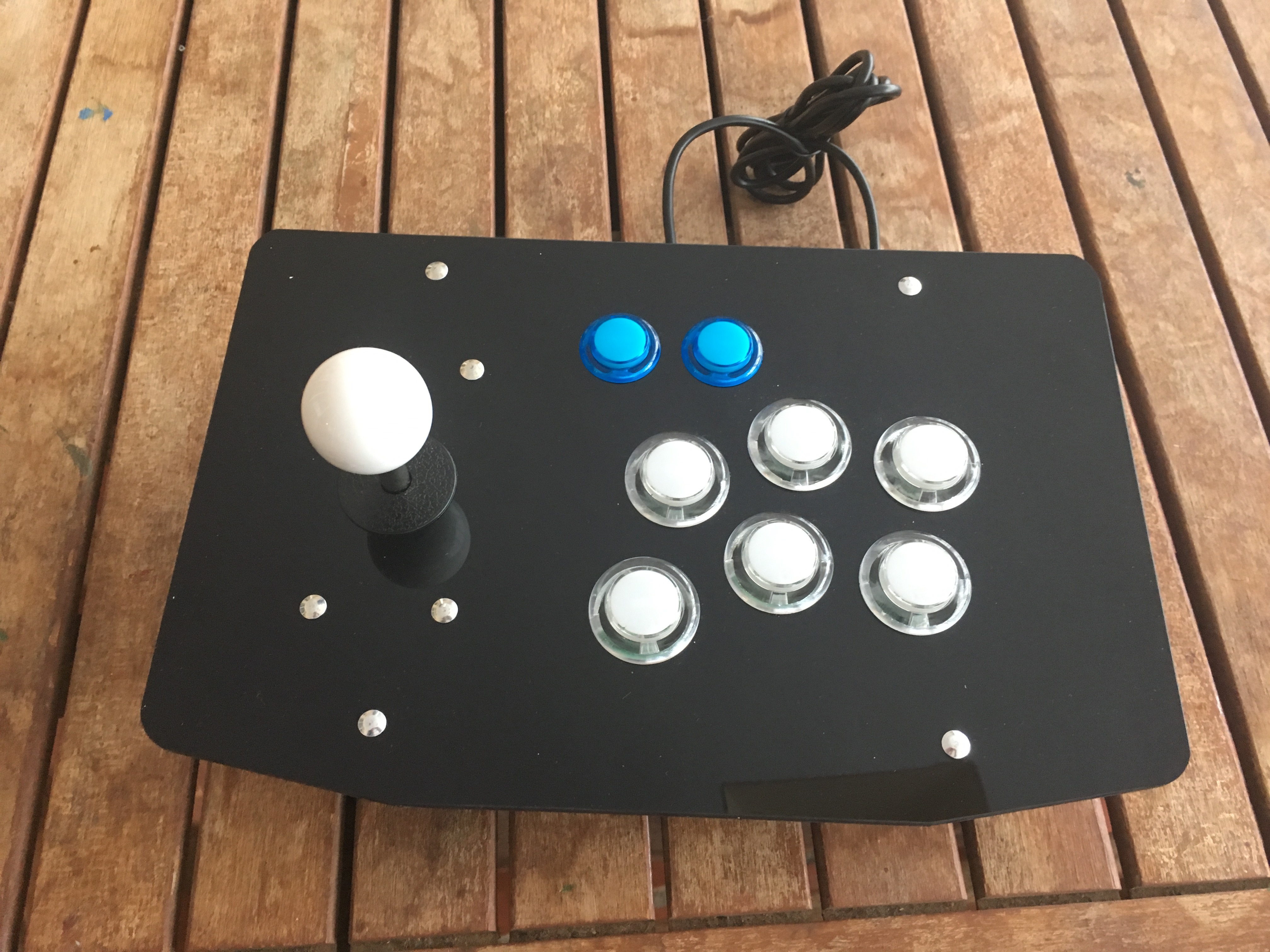
Your controller box should look similar to this at this stage:
Cabling the controller
Before mounting the Raspberry we need to cable the controller, so that we can find out where we will have space to fit the Raspberry, depending on the controler box you have purchased this may be more or less challenging. I suggest geting a box that is at least 5cm depth if you do not want to struggle (or want to avoid cutting GPIO pins off the Raspberry).
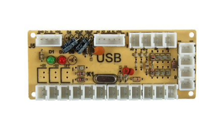
The USB Zero Delay controller is used to connect the joystick and buttons to the Raspberry through its USB interface:
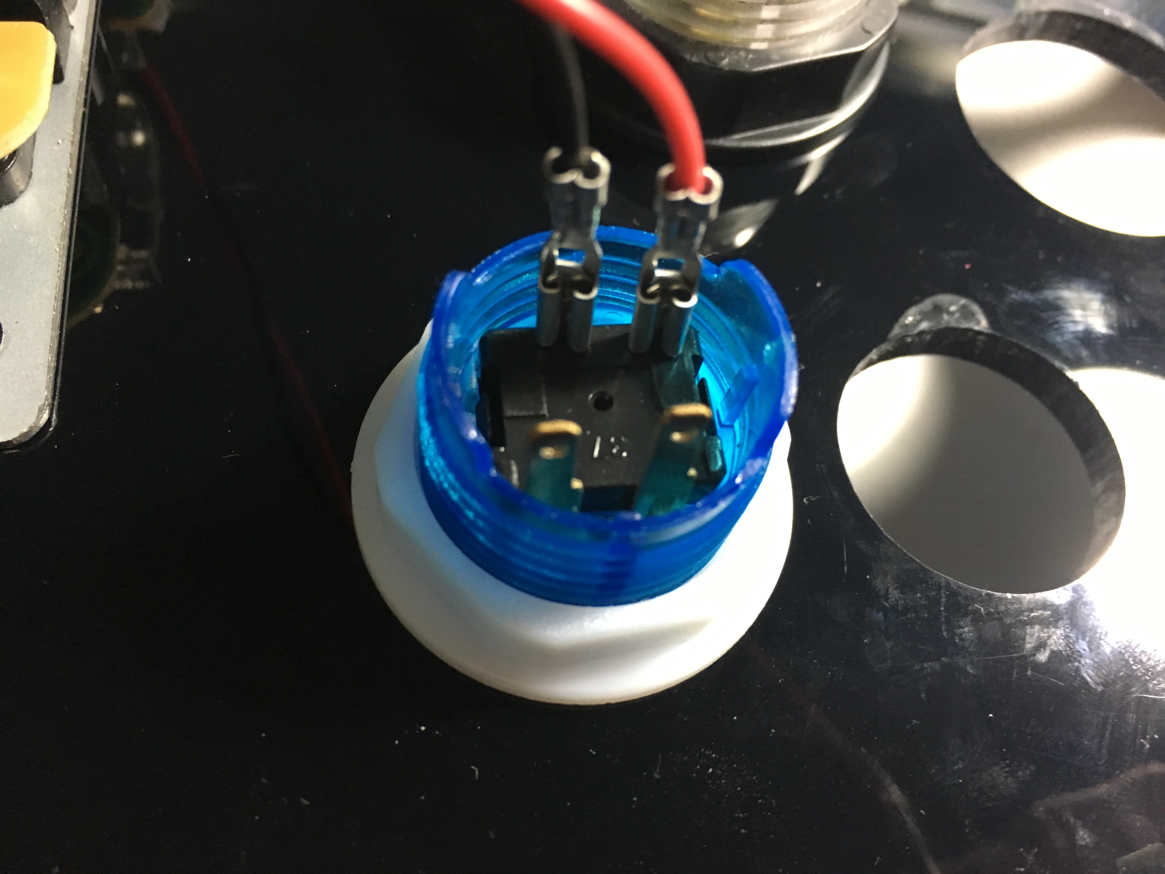
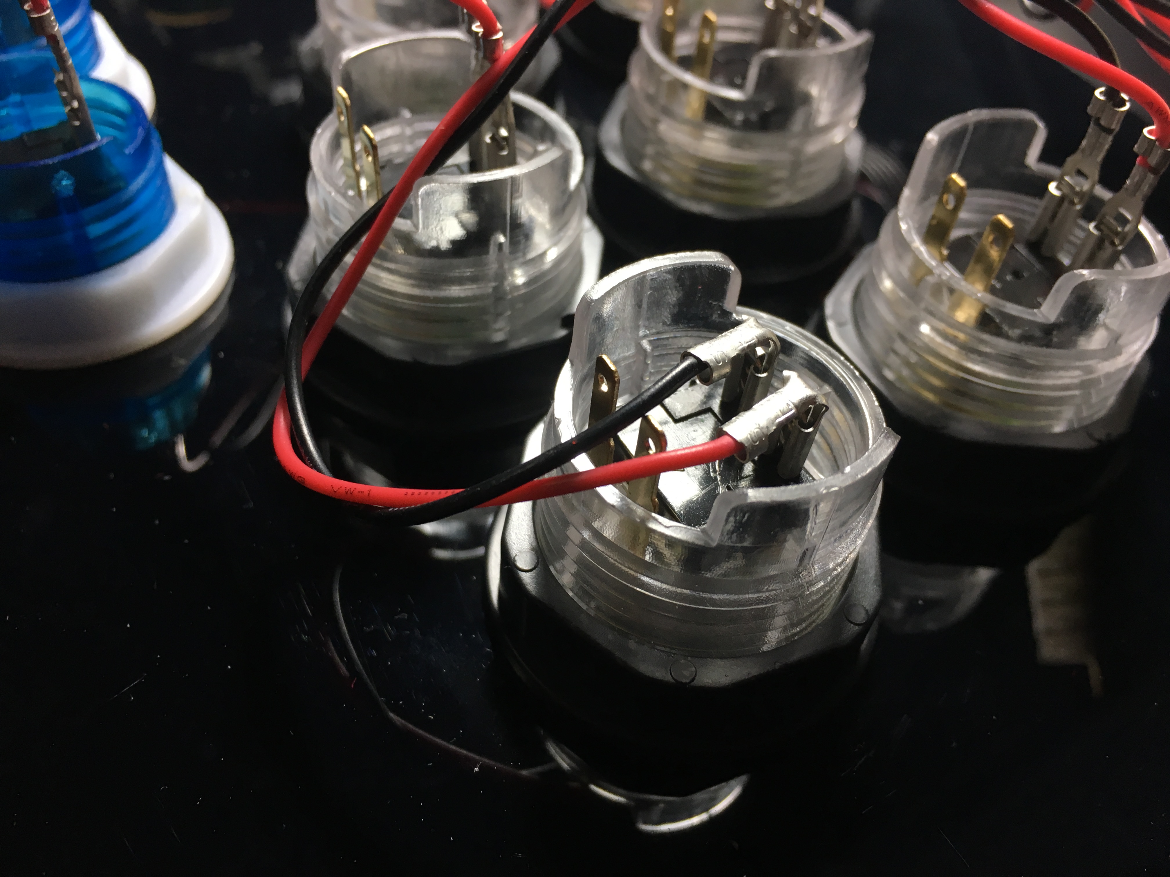
For the time being do not yet attach the USB controller to the box, just cable it in. Each button has two pins that connect to a socket in the USB controller: the connectors that attach to each of the button pins fits both ways however there is one position where the connector is securely attached and does not disconnect:
If your buttons have built-in LEDs you will have 4 pins per button, for the purposes of this tutorial we will ignore the LED wiring and just use the two innermost pins, as shown in the above image.
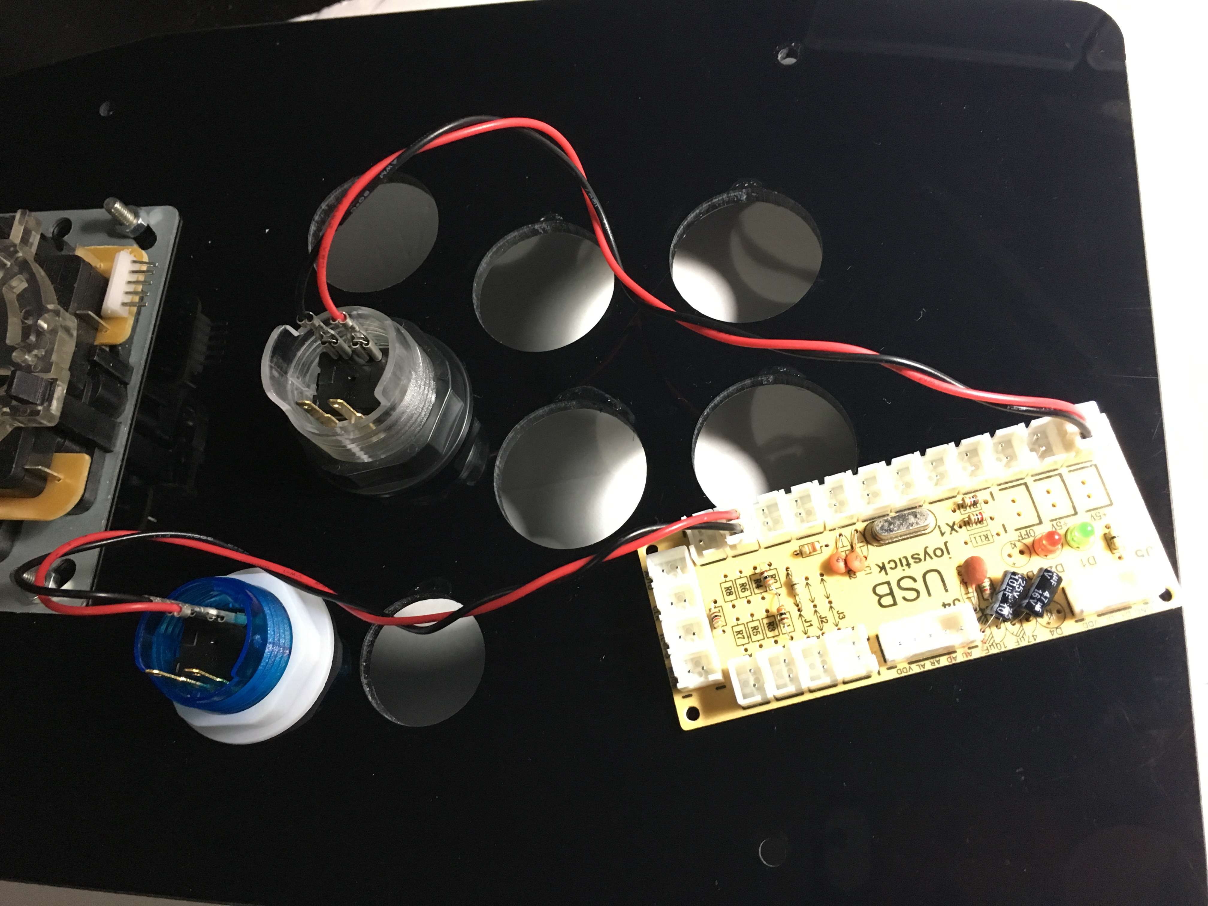
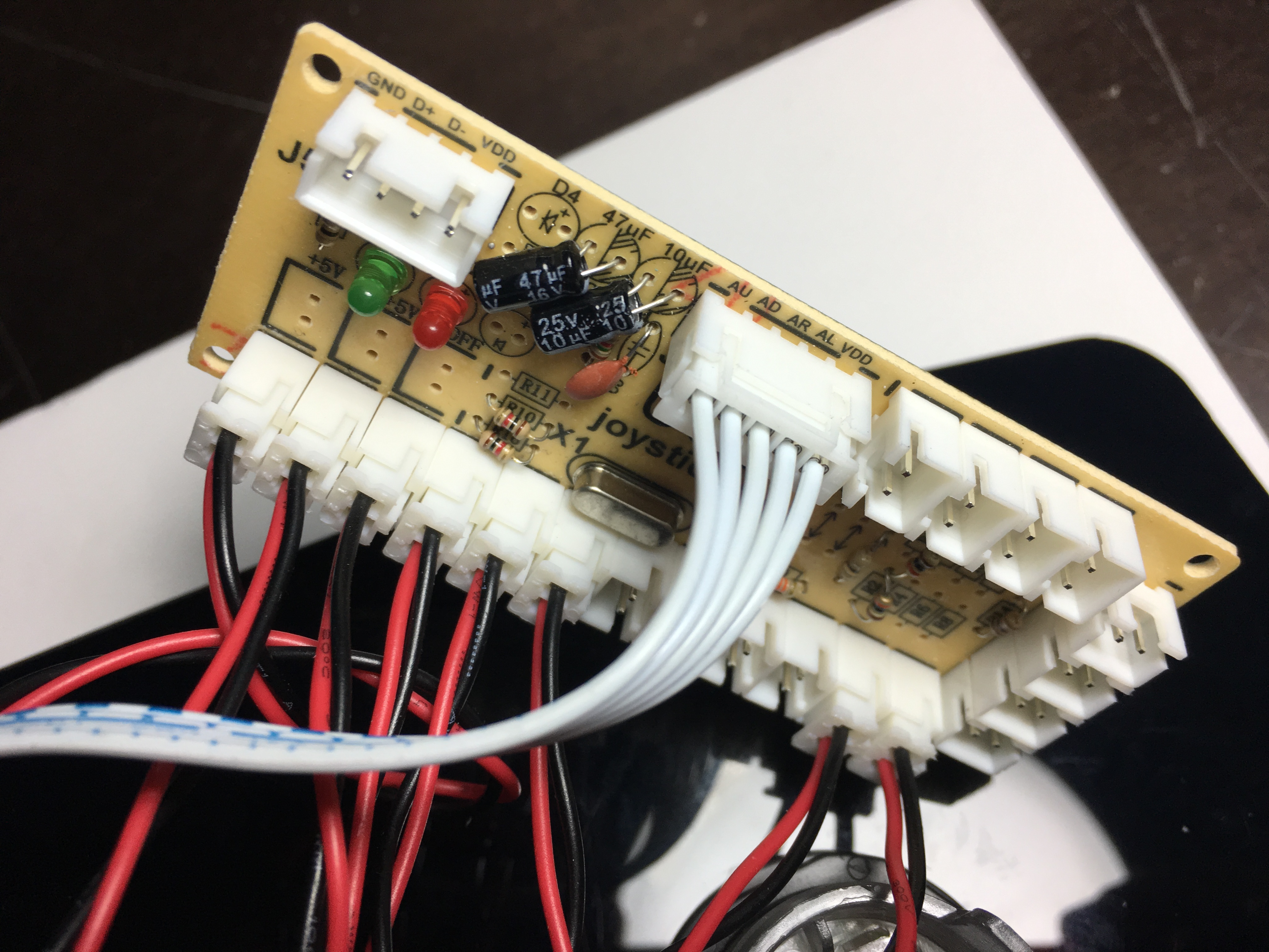
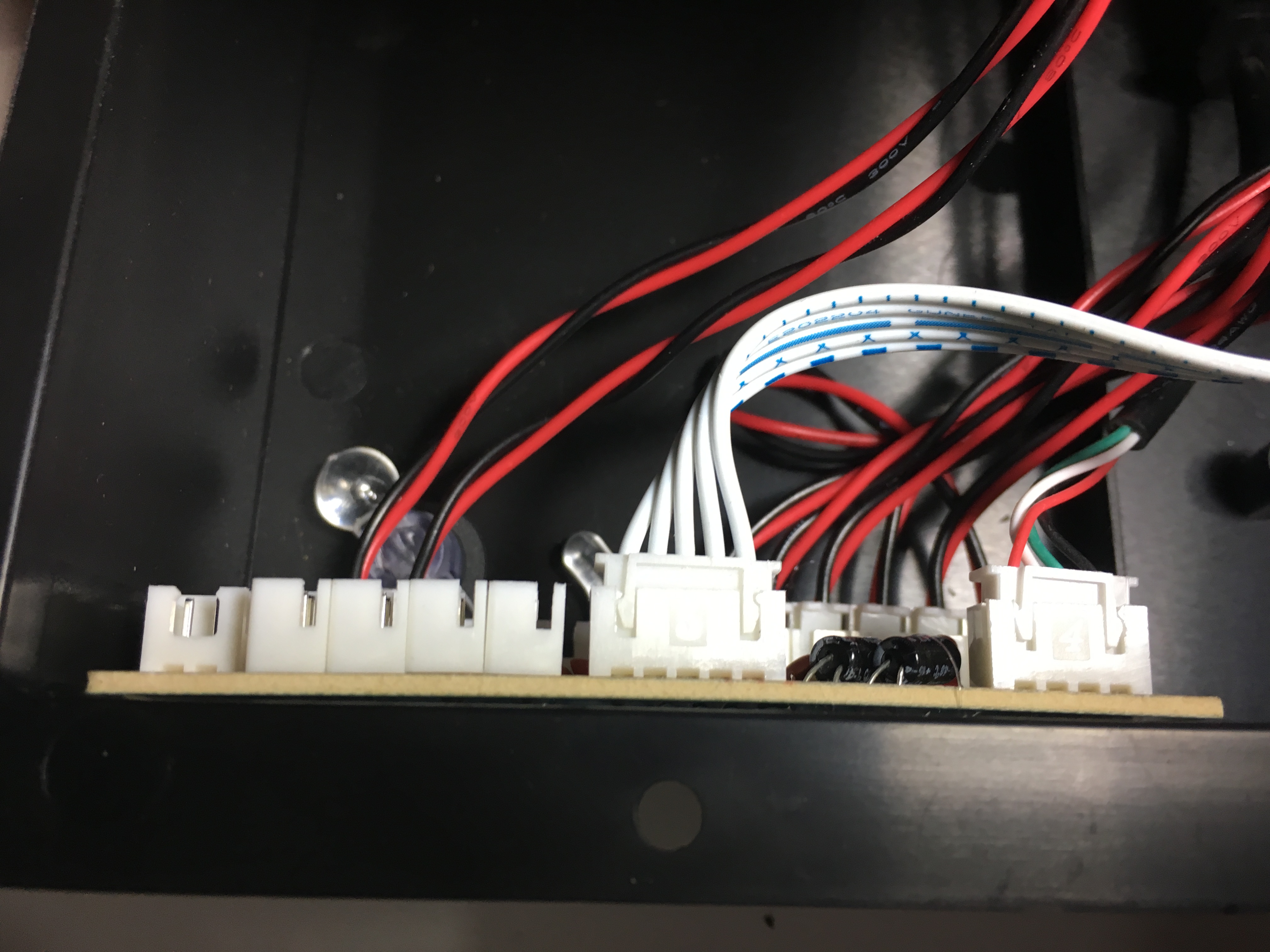
Once the pins are attached to the button, twist the cable before you attach the connector to the USB controller so that the cables are tidier, then repeat the process for all the buttons. It does not matter which connector you use for each button in the USB controller as long as you use the ones in the bottom row and you use the same schema always (if you plan to do multiplayer). Here is a suggested connection diagram that you can use:
The following image shows one of the normal buttons and one of the option buttons already cabled:
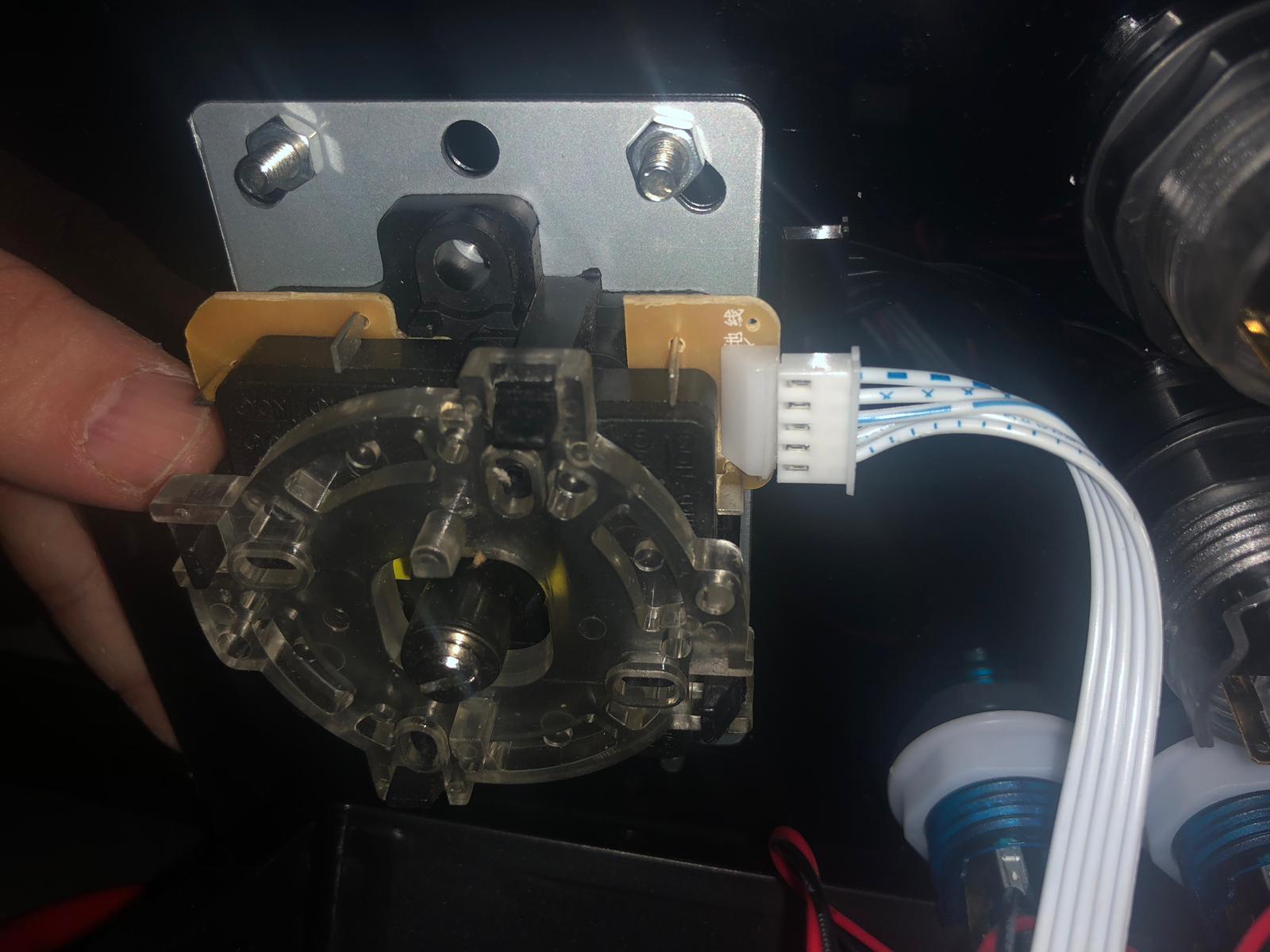
The joystick connection is a bit different: it uses a 5-wire ribbon cable that fits in the dedicated space in the USB controller, with notches that ensure it only fits one way:
The joystick side of the connection fits both ways: make sure you put the cable with the white side up, e.g. closer to the controller box cover (if you cable it the wrong way around you will have a joystick where only the “up” action works):
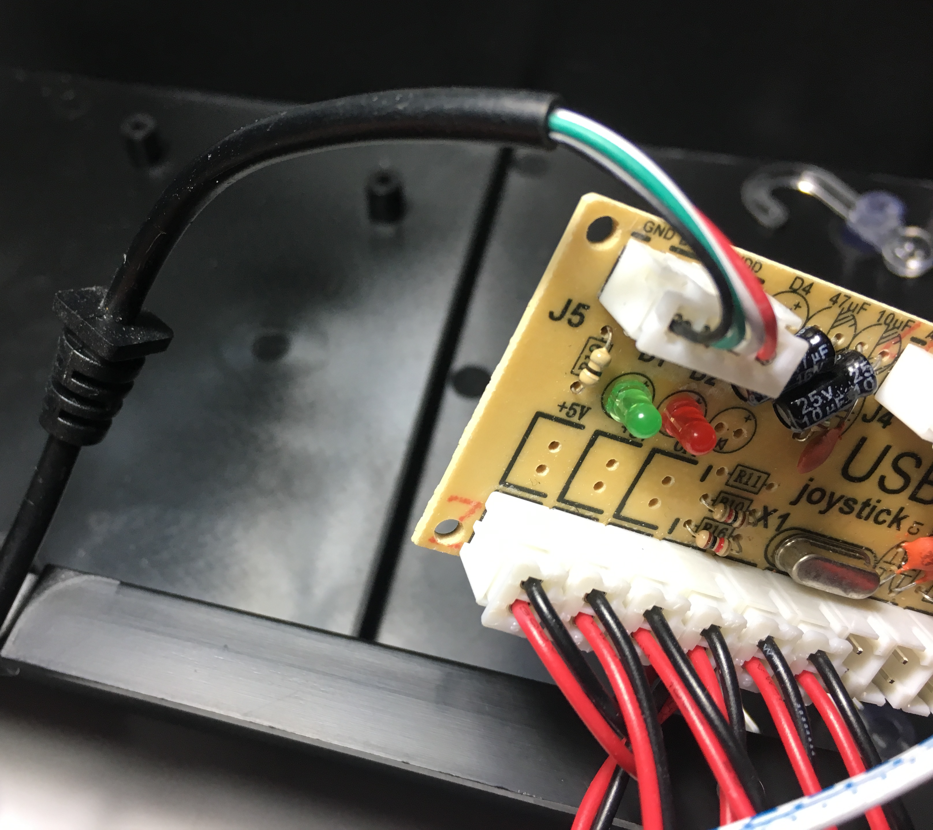
Finally the USB connector fits in its socket in the encoder, not much to say here:
Because we want the arcade controller to support more than one player (by chaining two arcade controllers to each other) and also to be used as an arcade controller for PCs and consoles we will keep the USB connector available externally; most of the times it will just be plugged in to the Raspberry but still keep the flexibility to:
-
If we want to play with more than one player, just plug the USB connector from the second controller to the Raspberry Pi of the first controller (and keep the first controller USB connected to the Raspberry).
-
If we want to use the system as an arcade controller for a PC or console, unplug the USB from the Raspberry and plug it in directly to the external device.
Mounting the Raspberry
Before you proceed, now is the right time to load the SD card with your preferred Raspberry Pi arcade emulator, I used RetroPie because it provides a nice compromise between simplicity and (if you really want) the ability to configure nearly every detail, just follow the RetroPie installation instructions. For my friends I installed the “spaceoddity” theme which makes it really intuitive.
Whatever you do, make sure the SD card is now inserted in the Raspberry Pi, and that it works before you mount it in the arcade controller - I can tell you it is quite painful to realise, after the box has been sealed, that you forgot to pop in the SD card :-)
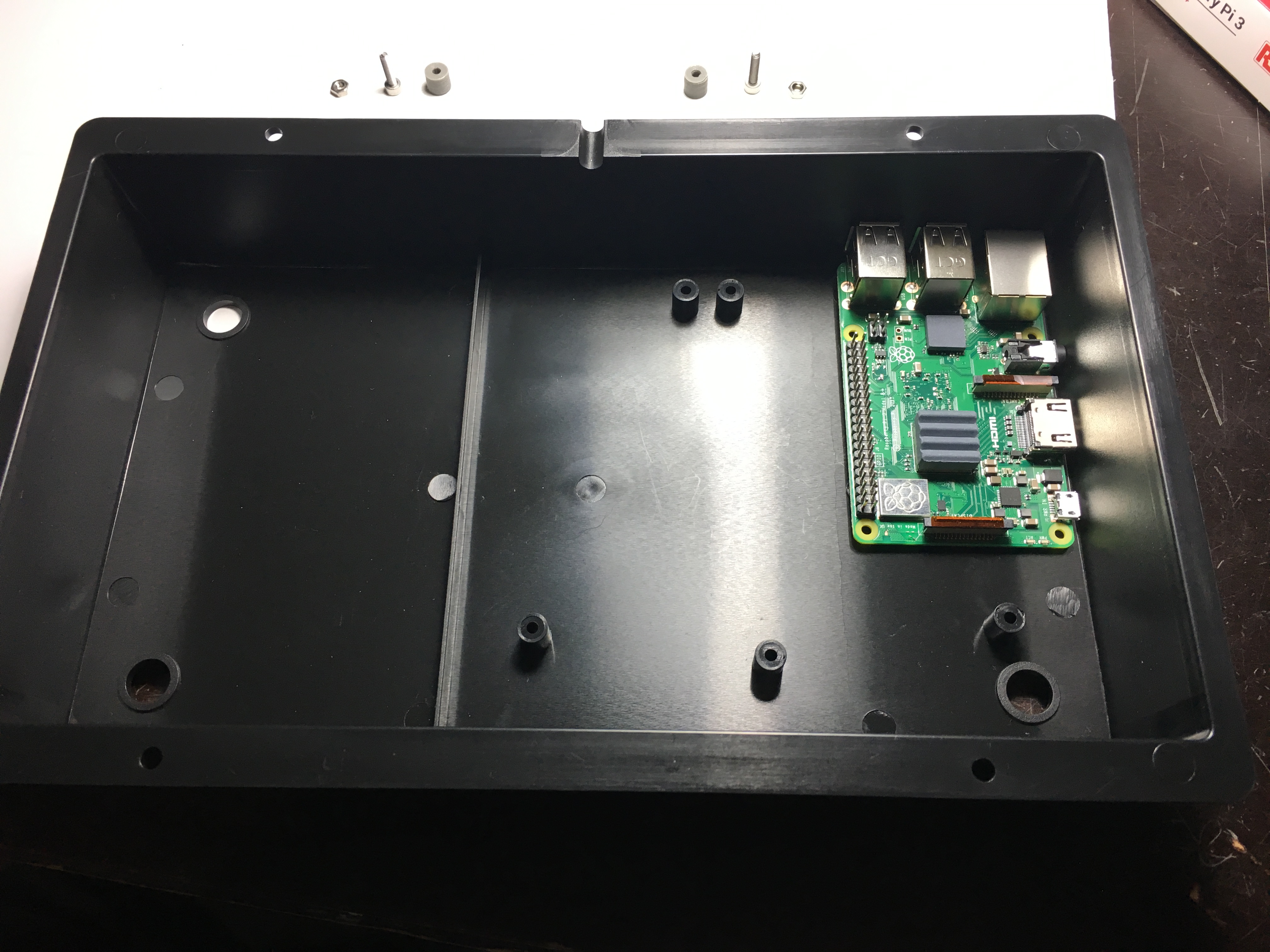
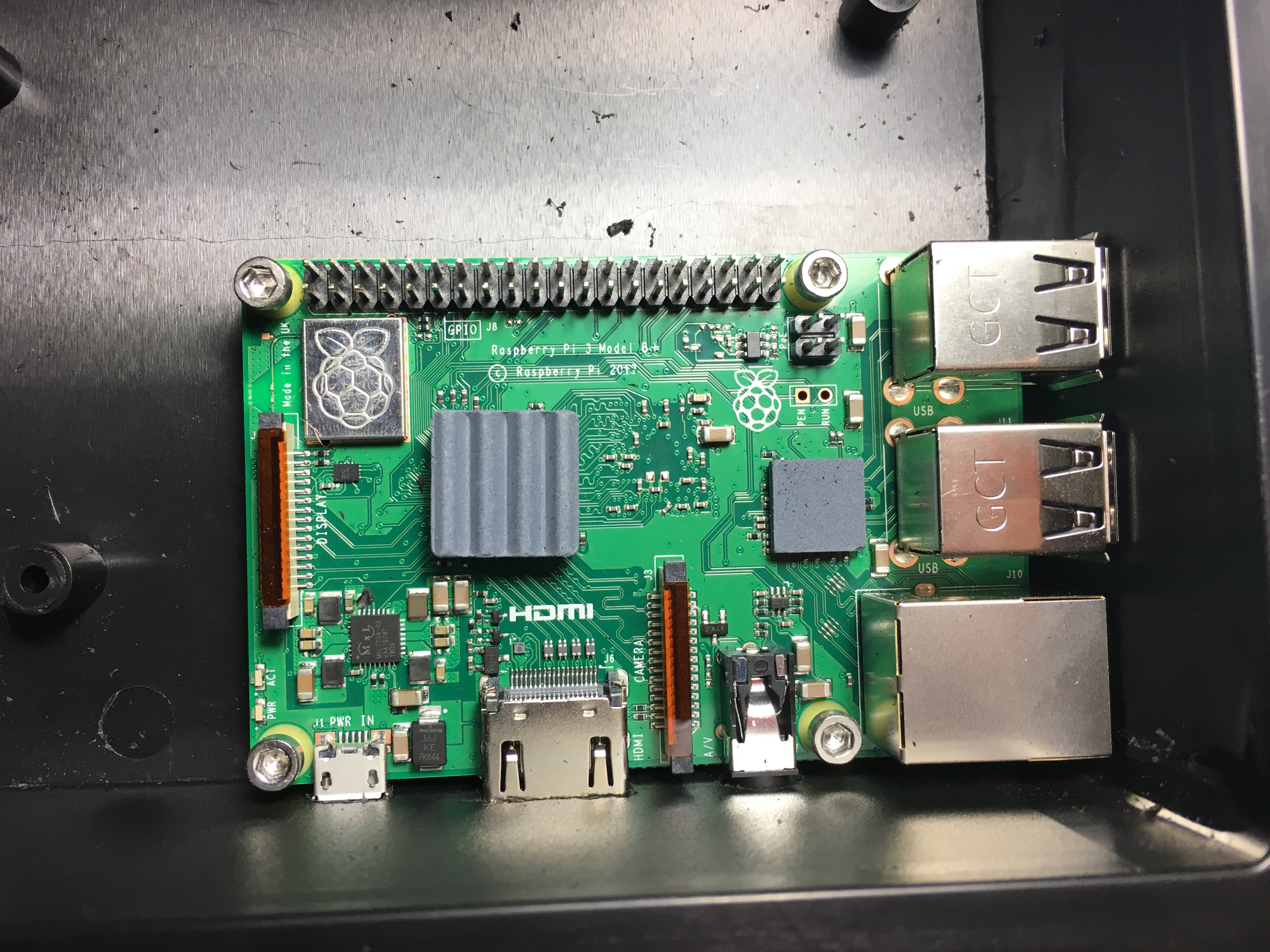
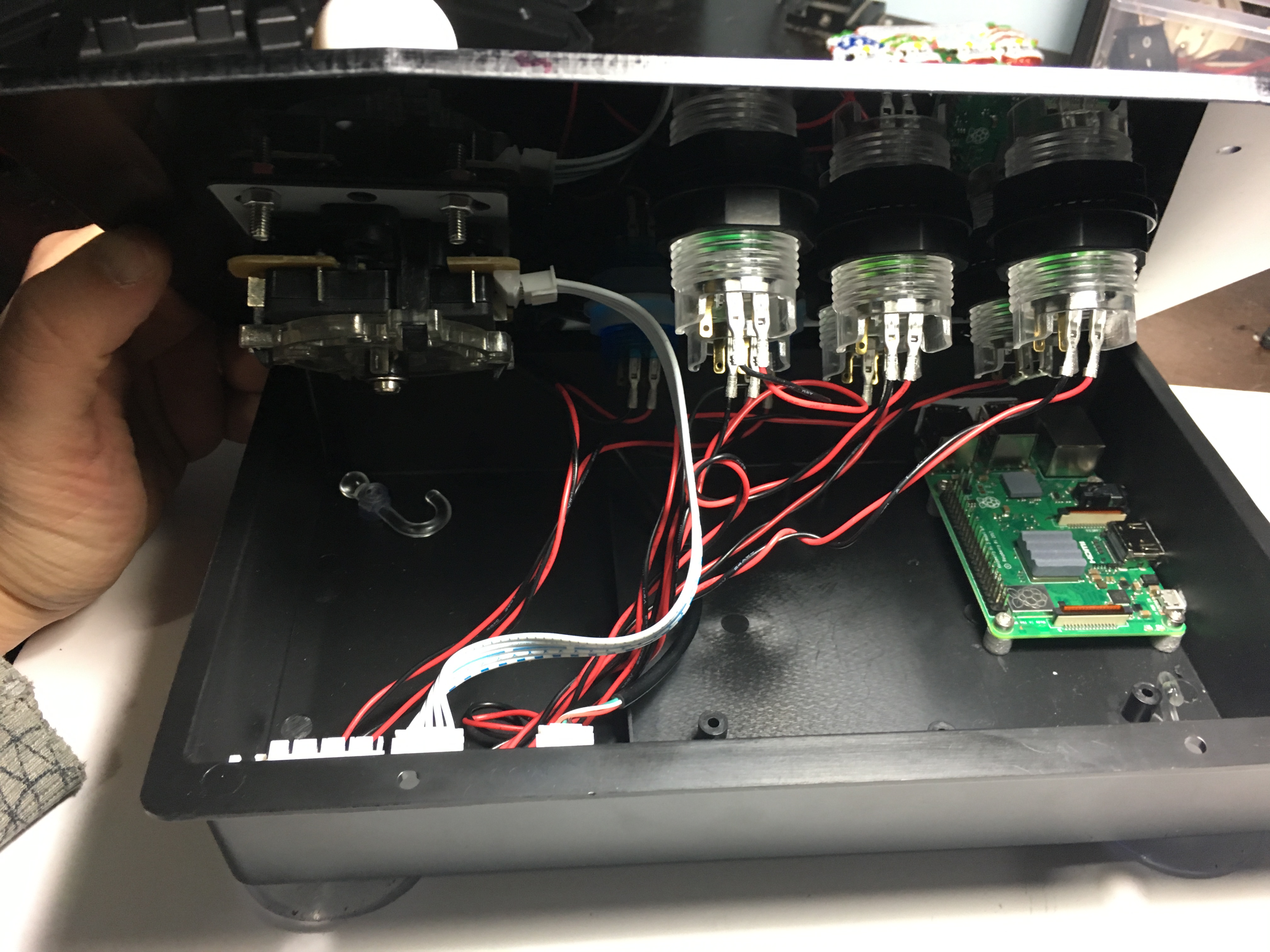
On to mounting the Raspberry Pi then… the controller box is 5cm depth, so the Raspberry must be mounted in a position where it does not interfere with the button or joystick back - while being able to expose the USB, micro-USB and HDMI ports to the outside: in our case the ideal mounting position for the Raspberry is the top-right corner:
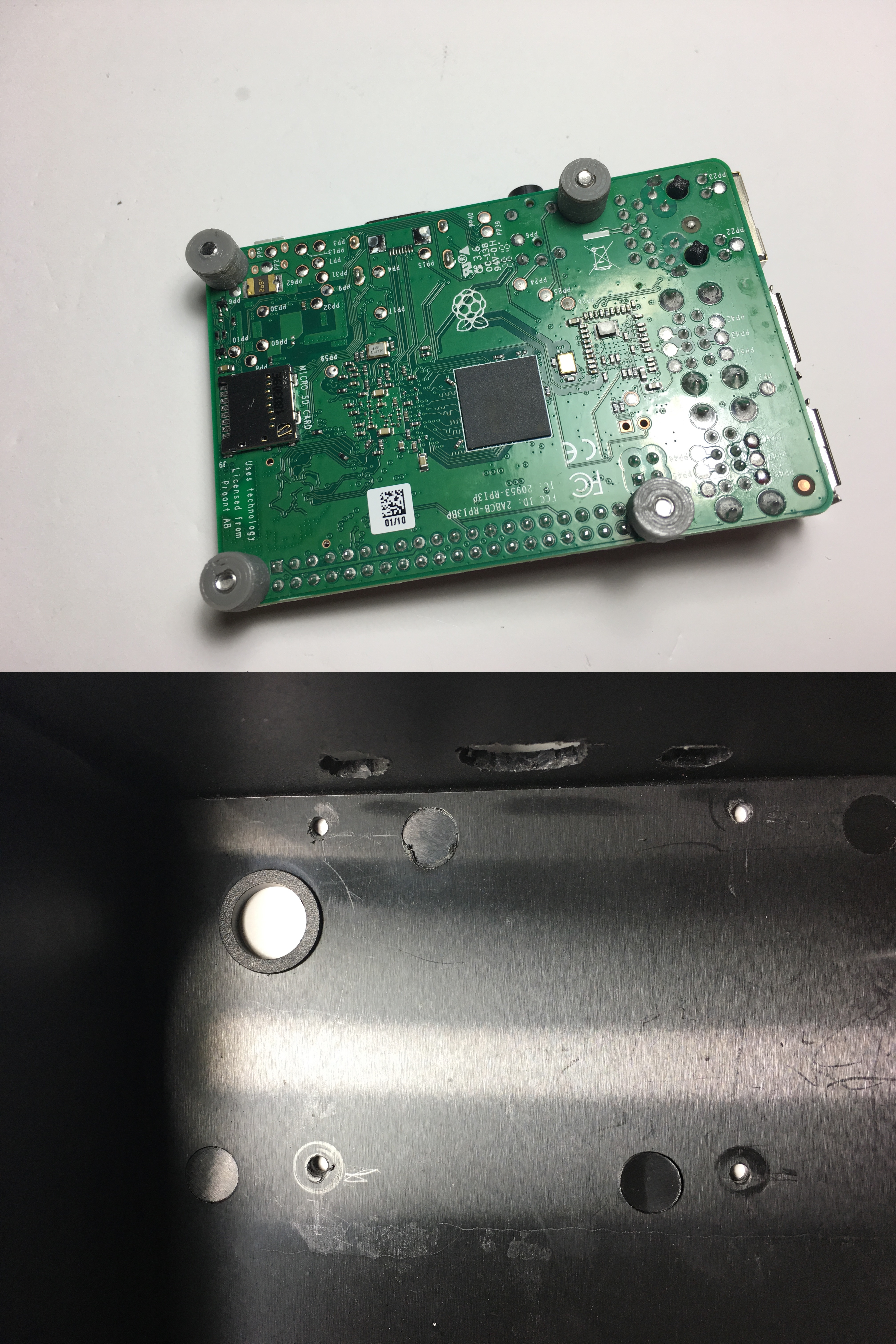
Because we want to be able to easily access the SD Card we will mount the Raspberry on top of standoffs, so that it is not just resting on the bottom of the controller box.
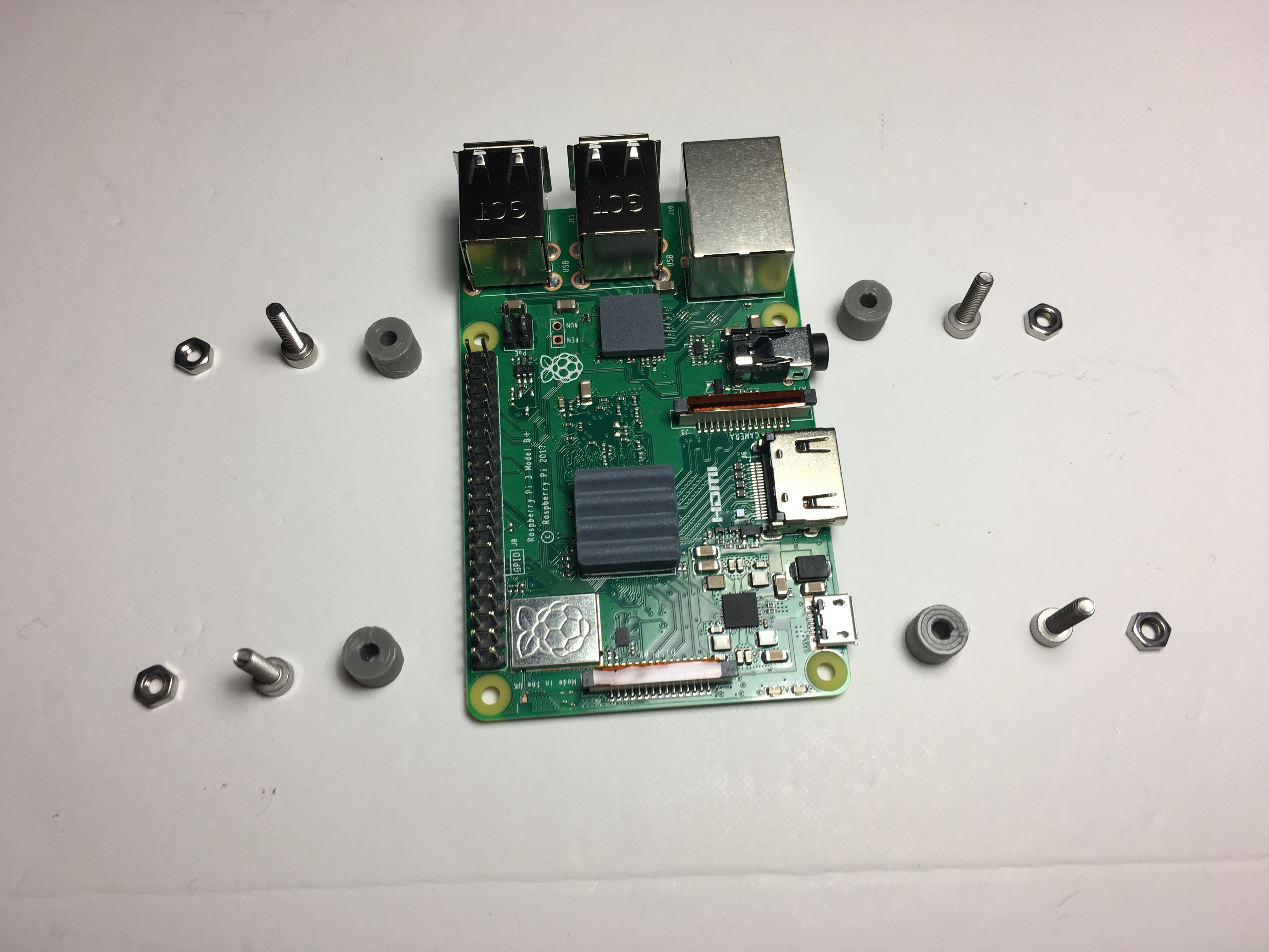
The Raspberry must be firmly mounted in the controller, as the exposed ports will get quite a bit of abuse - I tried using epoxy to mount it initially, however the bonding with the polypropilene of the controller box is not really that good and it did not withstand much tinkering with. In the end I ended up 3D printing standoffs and using M3x12 screws and nuts to secure them:
If you cannot 3D print the standoffs just find a piece of wood or plastic and cut it down to about 7mm of height, then drill with a 3mm drillbit.
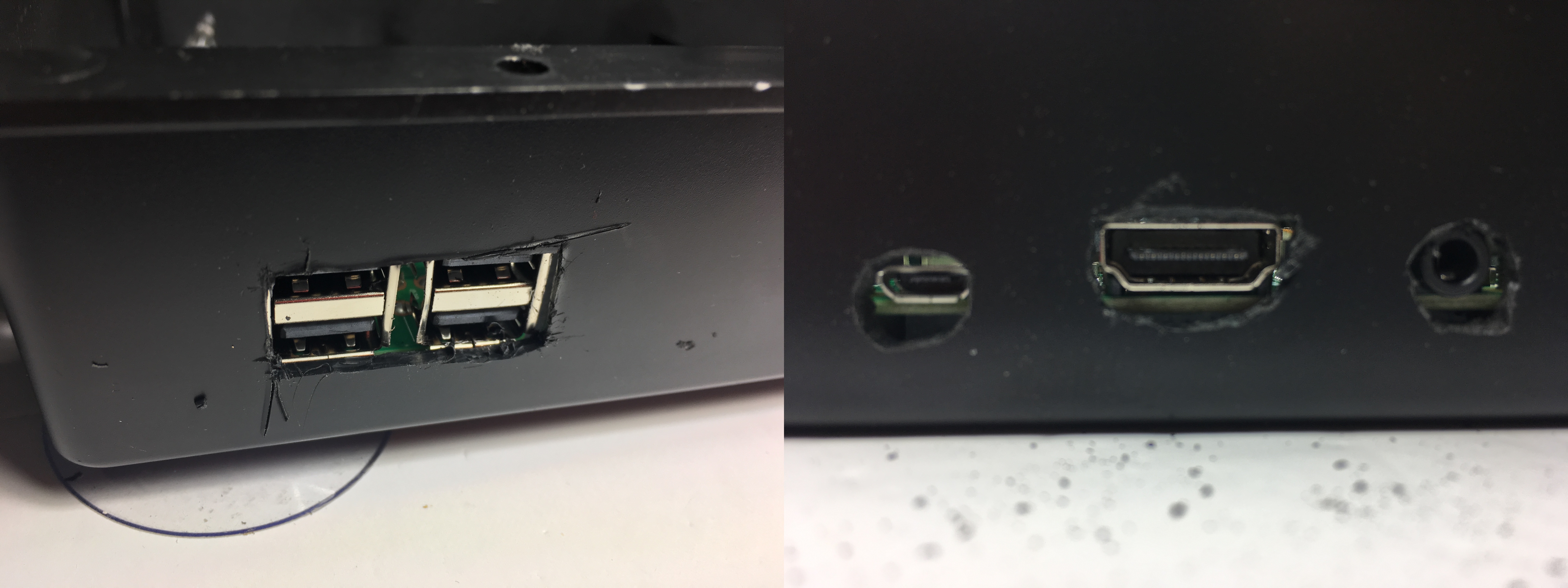
Mount the standoffs and screw them to the Raspberry Pi, but before you screw them to the box, mark the USB, HDMI and micro-USB connectors on the controller box side and front using a pencil, then use a drillbit plus Stanley knife to cut off the relevant sections until the connectors fit snuggly:
Cutting the holes was probably the most challenging bit of the whole project, if you have any tips for doing a better job please share them.
One you have the connector holes created, it is time to secure the Raspberry to the controller box - I simply pressed the Raspberry Pi to the box and the screws which were protruding from the bottom of the standoffs created a mark that I then used as a guide to drill through with a 3mm drillbit:
If your controller box has suckers, just before you screw in the Raspberry make sure you install them - otherwise the board may prevent you from installing them.
Once the Raspberry is secured, try closing the lid of the arcade controller and see if the board hits any of the buttons/joystick or cables. In my case the righmost button was colliding with the GPIO connector of the Raspberry so to avoid unexpected shorts I used pliers to bend the pins of the button:
Now is a good moment to find a final resting place for the USB encoder, in my case I tried the front side of the box (where the USB holes are) but there was not enough space, but there was no problem placing it on the back, as there is a very wide areas with no buttons. I used a glue gun to stick the encoder to the box:
Most of the work is done! Before you screw the box lid have a look and check that all the cables are in the right place:
It is not a bad idea to test the whole system at this stage before your close it in, it saves on a lot of unscrewing later on if something does not work as expected.
Connect the USB cable to one of the ports in the Raspberry Pi on the outside of the box, close the lid… and you are done!
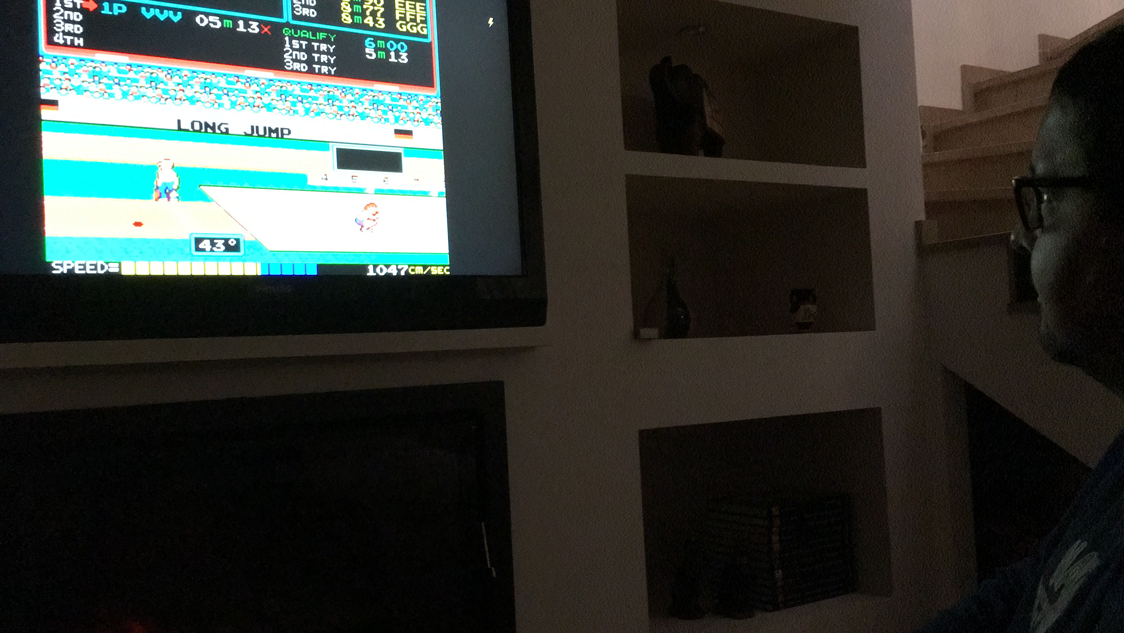
Just plug-in the controller to a power adapter, a HDMI input on your TV and get playing - here is a picture of a friend spreading some “Track & Field” love:

